
Iron vs steel: What are the Differences Between Metal, Iron and Steel
There are a number of complex tasks involved in the manufacturing of electronic assemblies, all of which can go wrong. In order to ensure quality standards are met, the fabrication of the printed circuit board assembly (PCBA), the placement of components on the board, as well as the quality of the parts themselves must be tested.
In addition to being time-consuming, the verification process can be expensive. In circuit testing (ICT) can be an effective tool for OEMs and contract manufacturers to consistently meet defined parameters during production runs.
Various PCB specifications can be designed depending on the application requirements in various industries. The designs range from simple with a single layer to complex with multiple layers assembled by soldering connections to hundreds of components. The result is a greater chance of defects and faults at the component level. Testing is therefore indispensable.
Testing ensures that the PCBs are in good condition by detecting many defects, including incorrect or missing components, defective solder joints, and short circuits among others. The most popular and widely used PCB testing method is In Circuit Testing (ICT). In this article, we will explore how ICT works.
PCBs are widely recognized as being the most cost-effective to test in-circuit. This is because its test time tends to be less than one minute, and the cost per unit is lower. The ICT method is more reliable than other testing methods since it tests each PCB component individually to identify:

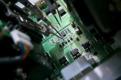
It is possible to perform ICT using a bed-of-nails test fixture or by using a flying probe set up to detect individual defects.
There are generally two parts to this test, namely, power-off tests and power-on tests. A power-off test detects shorts between traces and component leads, resistor values, and the presence of passive and analog components. In addition, this test ensures the jumpers/switches are set correctly.
In contrast, power-on tests are conducted to detect bad or incorrect analog and digital components, capacitance and inductance values, transistor beta values, and digital component timing. Besides these, power-on test also performs all the other tests aforementioned for power-off test.
The ICT process identifies potential defects in individual components and the components’ connections with a substrate. Additionally, the test can be run without power being applied to the unit under test, which makes it popular.
Following the test, a report containing points relating to coverage may be generated, including the list of components that have been tested, those that have been partially tested, and those that have not been tested, the type of fixtures used, and the software used. The PCB fabricator can carefully analyze the report after the testing has been completed and make changes as necessary.
During the test of each finished product for proper functionality, ICT uses test fixtures, commonly called “bed of nails” because they contain multiple contact pins. Engineers determine in advance how the bed of nails will access the critical test points of a printed circuit board assembly.
When a test point on the PCB assembly is in contact with specific pins on the test fixture, they will be compressed, either manually or by an induced air vacuum.
Engineers who are intimately familiar with the product’s built-in parameters and intended function are ideal candidates to develop the software required to execute the test on the assembly. Testing for potential problems is carried out by powering on/off certain areas, measuring electrical parameters, and identifying any anomalies.
In addition to increasing quality, ICT allows for better line speeds by automating the testing process. In order to maintain design standards, manufacturers need to be able to check each finished product quickly and consistently. Checks for regular configurations of the ICT include the following parameters and faults:
It is still common for mistakes to occur in the manufacturing process today, despite today's high standards and heavy reliance on automation. Quality inspection is routinely performed on ICT products.
During assembly, individual traces of PCBs are more susceptible to damage as they become more densely populated. ICT examines the PCB board for any short circuits or open circuits and isolates them.
The effects of electrostatic discharge on an IC may not be immediately noticeable during standard product operation tests. The technicians can locate and repair damaged components by measuring their reaction to specific voltages and currents.
The ICT can easily certify that the final product meets design specifications by measuring its resistance and capacitance.
Electronic products that are mass-produced can be tested to make sure they are operating properly using ICT. The in-circuit testing method is not a perfect method of testing, but it is one of the most efficient methods of producing large quantities of products that work as designed.
With more than 78 manufacturing processes, including electrical and electronics manufacturing, metal casting, metal fabrication, precision CNC machining, plastic fabrication, metal finishing and more, etc., in addition to our 200+ sub-contractor partners, OmnidexCN is able to support every project or component production regardless of the development stage or mass production.
To know more about our electronics manufacturing services for your next project, you may contact us directly HERE.
Contact our Customer Service and let us know how we can help to catapult your next project to success.

If you are looking for metal casting services, our brochure is a great way to discover what Omnidex has to offer. You can download HERE or EXPLORE HERE to learn more or .


If you are looking for metal casting services, our brochure is a great way to discover what Omnidex has to offer. You can download HERE to learn more.

Copyright © 2024 Omnidex. All rights reserved.